Focus Stacking Theory
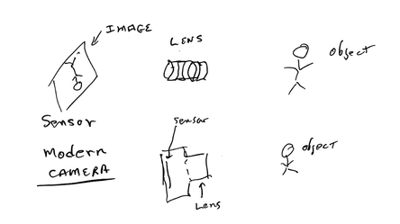
This discussion revolves around the real world cameras: Panasonic S1R and Nikon Z7 / Nikon D850. The real world stacking programs are Helicon Focus and Zerene Stacker. A modern electronic camera is represented by this sketch:
This discussion revolves around the real world cameras: Panasonic S1R and Nikon Z7 / Nikon D850. The real world stacking programs are Helicon Focus and Zerene Stacker. A modern electronic camera is represented by this sketch:
The lens focuses an image of the object of the photo on the sensor. The sensor records the image and turns it into a computer file composed of pixels or dots forming the image. Depth of field refers to the fact that the camera focuses at one distance and things closer or further are out focus (blurred) to a greater or lessor extent. The depth of field is considered the distance that the blurring is acceptable for parts of the object that are out of focus. The depth of field depends on the properties of the lens and how far away the object is from the camera. Higher f-number increases depth of field, but this is not free, as increasing the f-number lowers resolution due to diffraction.
Focus stacking creates a composite photo from a series (stack) of photos, each image in the stack focused a bit deeper into the object. The stacking program combines the sharp part of each photo to make a composite photo with much greater depth of field than is possible with a single photo. An example below compares a single photo with a composite photo. Stacking doesn't handle objects that are moving very well, usually creating multiple images in the composite photo.
Focus stacking creates a composite photo from a series (stack) of photos, each image in the stack focused a bit deeper into the object. The stacking program combines the sharp part of each photo to make a composite photo with much greater depth of field than is possible with a single photo. An example below compares a single photo with a composite photo. Stacking doesn't handle objects that are moving very well, usually creating multiple images in the composite photo.
How the camera performs auto focus for stacks
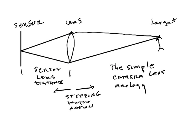
The lens focus is driven by a stepping motor, or possibly a servo motor. The action is analogous to stepping the sensor distance between the sensor and a simple camera lens.
A real camera lens is more complicated than the above illustration and may have internal elements that move at different rates. So, the sensor-lens distance is a bit of a fiction, but the analogy is useful. The sensor-lens distance moves by small amounts. For example, a 50mm lens is 50 mm away from the sensor when focused on infinity. In practical terms, infinity means a long distance from the camera, not literally an infinite distance. When focused at 500 mm the 50mm lens is 55mm away from the sensor. The sensor-lens distance changes by only 5 mm compared to focus on infinity. The movement of the focus point at the target is amplified by the action of the lens. For example, if our 50 mm lens is focused at 500 mm, reducing the sensor-lens distance by 1 mm from 55 to 54 mm, the focus at the target will move 100 times more, by about 100 mm, from 500 mm to 600 mm.
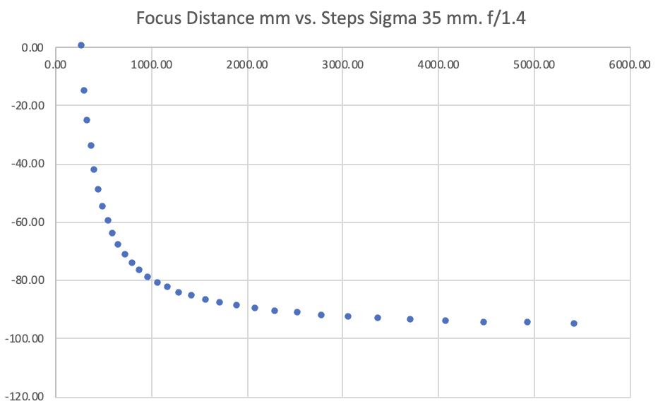
The basic action is that as the lens is stepped to the left, the focus point moves to the right and vice versa. There is a functional relationship between the steps the lens is moved and the focus distance. My convention is that the step count is zero when the lens is at its closest focus and the step count steps negative as the focus point moves away from close focus. Eventually the focus point reaches infinity and the step count reaches a negative value corresponding to infinity (for the step multiplier set to 10). This functional relationship can be memorialized by an interpolated table or a mathematical function. Since there is no simple lens, but a thick lens of variable thickness, the focus distance is most conveniently measured not from the lens but from the sensor surface. Most cameras have a symbol on the body, a circle with a vertical line, that shows the location of the sensor surface and thus provides a mark to make measurements from.
The basic action is that as the lens is stepped to the left, the focus point moves to the right and vice versa. There is a functional relationship between the steps the lens is moved and the focus distance. My convention is that the step count is zero when the lens is at its closest focus and the step count steps negative as the focus point moves away from close focus. Eventually the focus point reaches infinity and the step count reaches a negative value corresponding to infinity (for the step multiplier set to 10). This functional relationship can be memorialized by an interpolated table or a mathematical function. Since there is no simple lens, but a thick lens of variable thickness, the focus distance is most conveniently measured not from the lens but from the sensor surface. Most cameras have a symbol on the body, a circle with a vertical line, that shows the location of the sensor surface and thus provides a mark to make measurements from.
Although a lens designer might be able to produce this function analytically from his lens designer software, for practical purposes the function must be determined by taking measurements of an actual lens utilizing the ability of the camera to take steps and capture corresponding images using the photo stacking facility.
Although the sensor-lens distance may be a fiction, it is clear that the camera stepping motors move elements of the lens by steps and that results in changing the focus point by nonlinear steps as shown in the above graph. Focal length is a characteristic of lenses, but for complex camera lenses, especially macro lenses, the focal length may vary substantially over the focal range. (A macro lens is used to greatly magnify small objects.) To assign a step size it is more practical to use reproduction ratio or its inverse magnification. For macro lenses the reproduction ratio is often presented in the focus indicator window that many lenses have. At reasonably long distances (d) these parameters are given by:
R= reproduction ratio= d/f (f is the lens focal length).
M= magnification= 1/R
At high magnifications the above formula no longer applies. If the reproduction ratio is 10 it means that the target object is 10 times larger than it appears on the sensor.
The relation between the size of a step in the sensor-lens distance and the step in the target distance is given by:
Target focus distance step = (m^2)*(sensor-lens distance step)
If the magnification is 10 then, m^2 (m squared) is 100 and a small movement in the sensor-lens distance is magnified by a factor of 100 on the target side.
Taking the 35 mm Sigma lens, the smallest step possible in sensor-lens distance is about 8 um (millionths of a meter). If the target is 35 meters away, then the reproduction ratio is 1000 (35000/35). and its square 1,000,000. The 8 um movement is amplified to 8 meters.
The reproduction ratio for close focus points can easily be measured by observing a ruler with the camera and comparing the width of the sensor with the number of mm visible on the ruler. For example the sensor is 24 x 36 mm on these cameras. If a ruler is imaged and 96mm of the ruler is visible in landscape mode, then the reproduction ration is 96/24 or 4.
Determining the potential sharpness of a stack
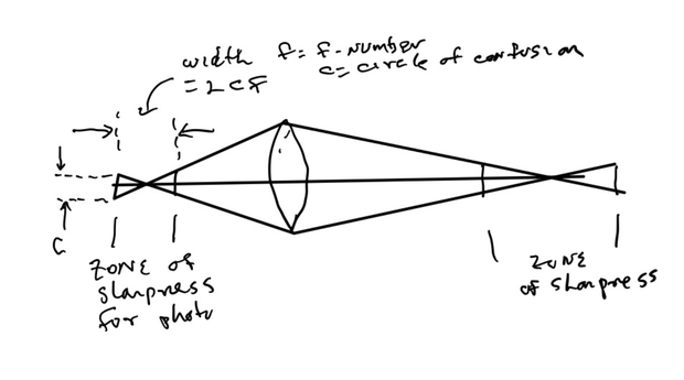
Successive photos in a stack have a separation in the focus points at the target. A corresponding and smaller separation exists in the sensor-lens side of the lens. Between two successive photos the image is slightly out of focus. The less the separation between photos, the less the loss of sharpness due to the out of focus condition for objects between the two photos.
In the diagram, the light from the lens is modeled as a cone that reaches a point of maximum sharpness and lesser sharpness to the right and left of the focus point. This zone of acceptable sharpness has a length related to the maximum increase in the circle of confusion and the f-number of the lens. (The circle of confusion refers to a loss of sharpness in the image because a point is imaged not as a point on the sensor, but as a blurry circle.) At the sharpest focus there is still a circle of confusion due to lens aberrations and diffraction. (Diffraction refers to a loss of resolution due to the wave nature of light that is unavoidable, even with a perfect lens.) The separation of the photos augments the existing circle of confusion. [A high-quality lens might have a circle of confusion of 5 um due to aberrations. The circle of confusion due to diffraction is given by 1.3*f-number. This is 10 um for f/8. All the circles of confusion add together to create the total.]
Defining the acceptable increase in the circle of confusion, “additional circle of confusion,” can determine the step size that should be utilized to limit the increase in the circle of confusion due to loss of focus between successive photos.
For macro lenses, the f-number is specified when the lens is focused on the furthest point, often infinity. When focused at the closest possible point the f-number will be smaller, often doubled. This change in f-number is generally ignored and is compensated for by the camera's dynamic response to light. In a stack the photos may be spaced more closely than needed to meet the circle of confusion criteria when the macro lens is close focused and the f-number is increased.
The Photo Stacking System Used by Nikon and Panasonic Cameras
The spacing between photos will be greater for larger f-numbers, as greater depth of field is associated with larger f-numbers. The camera has a basic step size that depends on f-number and that is multiplied by a multiplier from 1 to 10. On the S1R the multiplication is literally from 1 to 10, but on the Nikon the steps between numbers are by a factor of about 1.25, but varying. The full range from 1 to 10 corresponds to a change in step size of a factor of approximately 8.5.
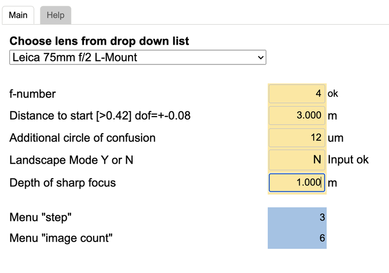
The size of the step between images is determined by the basic step size. The camera modifies the basic step size according to f-number. In theory, ideally, the basic step size will double if the f-number doubles. The menu step multiplies the basic step size by a value from 1 to 10 or a table value on the Nikon. For example, the Sigma 70mm f/2.8 L-mount macro lens, the basic stepsize, closely follows this proportional relation between basic step size and f-number. Some lenses achieve this proportionality. Others will have larger or smaller departures from proportionality, presumably due to limitations of the operation of the stepping motors or software problems. A sample screen of my app that computes the necessary camera menu inputs to acquire a stack is shown below.
A number of different lenses are handled by the app. The lens is selected using the dropdown list shown above. The user must supply the f-number the camera is set to, the additional circle of confusion desired, the distance of the start of the sharp zone and the depth of the sharp zone. The app returns the menu step multiplier and the number of images or photos. The user must then focus the camera on the start of the stack and triggers stack acquisition.
If "Landscape Mode" is enabled, then a different operation is assumed. In this case the app only pays attention to the f-number and the additional circle of confusion. The app only returns the step and the image count as an arbitrarily large number. The user must focus on the start of the sharp zone and trigger stack acquisition. The stack acquisition will continue until the camera reaches focus infinity (and usually a bit more). This results in a stack sharp from initial focus to infinity. This mode is appropriate for taking pictures of landscapes.
Handheld Stacks
Typically, a tripod is used when acquiring a stack. An alternative is to hand hold the camera with stabilization enabled. To keep the camera pointed close to the target a shotgun type sight such as the Olympus “EE-1 Dot Sight” can be used. The shotgun sight is most relevant for the Nikon cameras because the viewfinder is disabled during stack acquisition. On the Panasonic S1R the viewfinder continues to work, but the shotgun sight may give a wider view of the scene. The sight mounts on the camera hot shoe, present to hold flash attachments or other devices. The stacking programs adjust the individual photos to be in registration, one with another, so some shake of the camera is tolerated. Handheld stack acquisition is unlikely to work when working at high magnification, when camera shake is magnified by the high magnification and the magnification varies due to shake in camera-object distance..
Using a Motorized Rail to Acquire a Stack
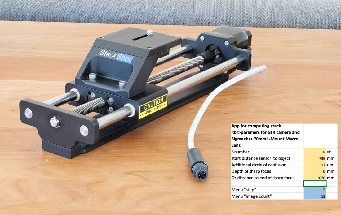
Instead of changing focus to take a stack, a motorized rail moves the camera (or the targeted object) stepping in either direction to increase or decrease the distance between the camera and the targeted object. The rail's computer controls the camera shutter via a cable that mimics a remote shutter controller. The Stackshot motorized rail, manufactured by the Cognisys company is shown below.
Instead of changing focus to take a stack, a motorized rail moves the camera (or the targeted object) stepping in either direction to increase or decrease the distance between the camera and the targeted object. The rail's computer controls the camera shutter via a cable that mimics a remote shutter controller. The Stackshot motorized rail, manufactured by the Cognisys company is shown below.
The motorized rail solution is more general because it can be used with any camera and manual focus mode lenses. Obviously the motorized rail is only good for a short depth of field, not exceeding the length of the rail, about 20cm for the device above. Refocusing the lens to acquire a stack is more versitile, because focus can slew over a much longer distance than a motorized rail. By changing focus as a stack is acquired, the depth of field can be very large, even from about 25 cm to infinity in the case of macro lenses.
Perspective can be an issue in a stack because the position of the observer changes as the stack is acquired. In the case of a focus created stack, the lens (considered the observer) moves away from the object as the stack advances. This is minor, except for some macro lenses. In the case of the motorized rail the change in perspective can be radical if the travel is long and the distance from the camera to the object is relatively small. A radical change in perspective can destroy the stack. For example as the camera moves different objects in the target move relative to each other, or one part of the object may block another part as the stack advances. Photos of tiny objects, such as insects, are best suited to the motorized rail. It can make small and precise steps. The highest magnification macro lenses don't autofocus and thus are most practical to use with a motorized rail.
